Downed Conductors from Arc Damage
Categories:
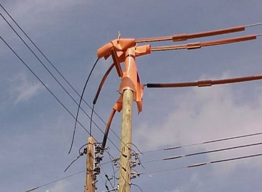
Should a Mylar balloon cause a downed conductor on a distribution line? How is that? The mechanical impact of a Mylar balloon is obviously quite small. So, how does a conductor fail? Often, the answer is arcing damage. The Mylar balloon causes a flashover, and the fault-current arc melts and damages a conductor enough for it to break and fall to the ground. The arc itself generates tremendous heat, and where an arc attaches to a conductor, it can weaken or burn conductor strands. Here is an example where a balloon-caused fault broke two of the conductors in about 0.1 secs (the total fault was almost one second long):
Mylar Balloon Causing Downed Conductors
This is called a burndown. Burndowns are most common with small conductor sizes and with covered conductors. It’s not just Mylar balloons. Squirrels and other animal faults, conductor slap, tree limbs, and lightning can all cause faults without causing mechanical damage. Any of these can trigger arc damage and burndowns.
Burndowns can cause public safety hazards if they lead to live, downed conductors. They may also trigger wildfires.
A well-designed distribution circuit should rarely have burndowns. A conductor burndown is a sign of problems on a circuit. A number of options are available to reduce arcing damage and burndowns, including faster relaying and/or fusing. Conductor damage is a function of the magnitude of the current, the duration, and the movement of the arc.
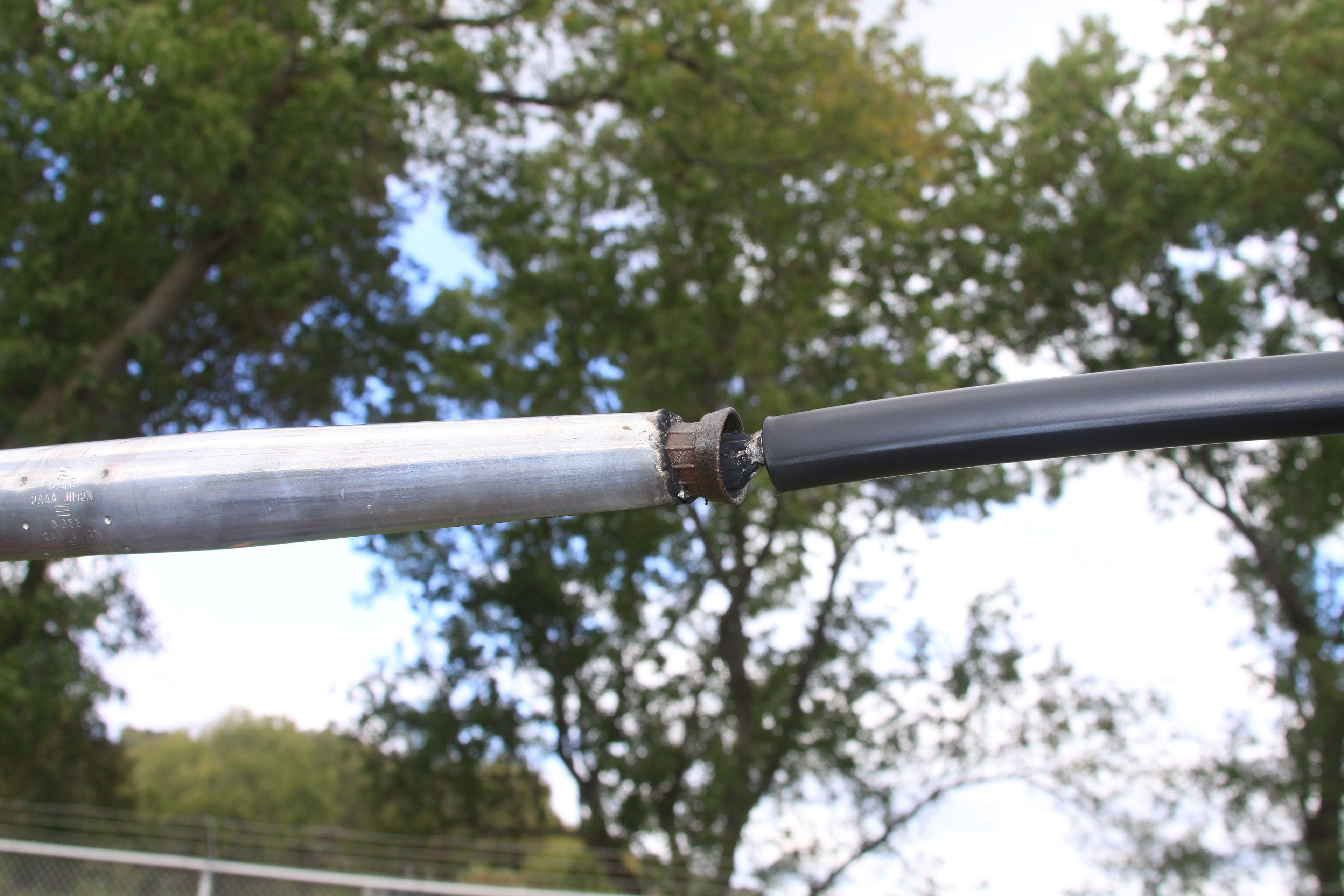
Note that arcing is not the only cause of downed conductors from faults. Failure of in- line connectors from the thermal and mechanical stress of the fault current can also cause downed conductors. These are also a function of magnitude and duration of the fault.
Arc Movement
Movement of the arc is an important consideration. The heat from the arc is what causes the damage. Although ionized air is a fairly good conductor, it is not as good as the conductor itself, so the arc gets very hot. On bare conductors, the arc is free to move, and the magnetic forces from the fault cause the arc to move in the direction away from the fault current source (the substation). This is called motoring. Here is an example of multiple reclose events for a fault caused by a tree limb.
Fault from a tree limb, EPRI Lenox Laboratory
Note the “bird-caging” damage to the conductors during this event. Hot gases from the arc anneal the conductor.
Line Equipment that can Constrain Arcs
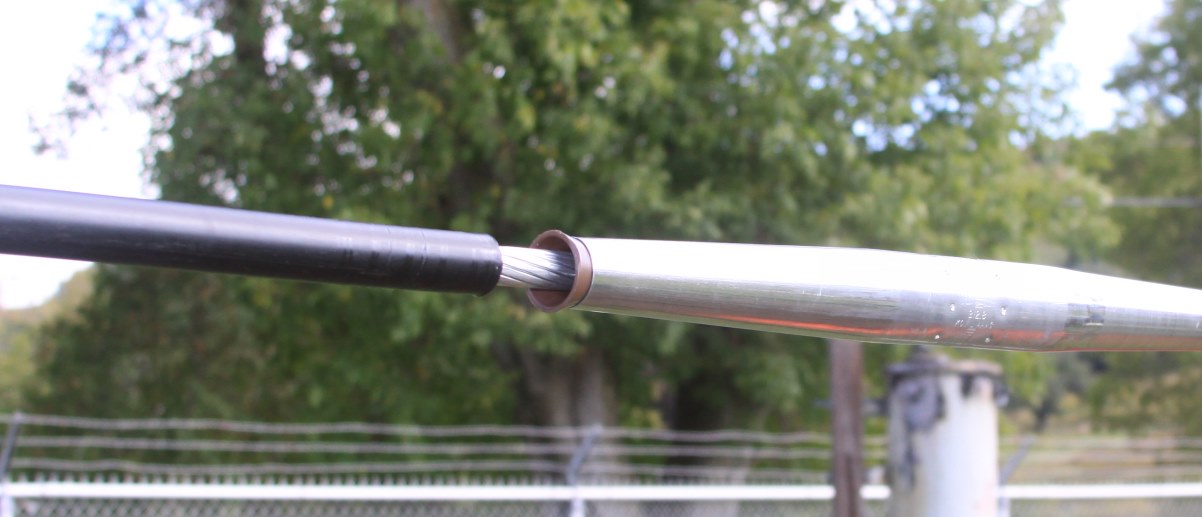
Arcing damage worsens when any equipment restricts movement of the root of the arc where it attaches to a conductor. If equipment constricts the arc to one location, the heating and melting is concentrated on one part of the conductor. The conductor can burn apart at the interface to the equipment. Covered conductors are a prime consideration, but several other scenarios are shown below.
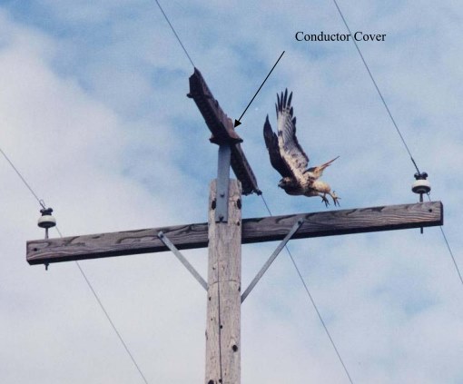
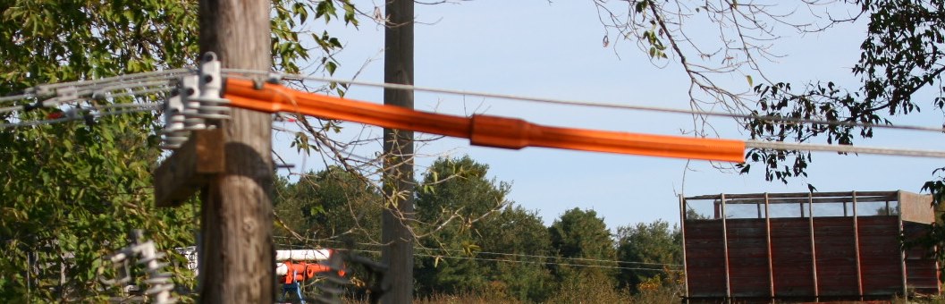
Rubber coverup is especially an issue for line workers. The possibility of burndowns and arc flash near energized work is an issue for worker safety. In the case study below, a fault happened midspan, and the arcs motored to the rubber cover and burned down the conductors. In this case the conductor was 4/0 ACSR, I = 4 kA, and t = 61 cycles (EPRI 1018694, 2009 1).
Here is an example of tests of arcing with covered conductors at an automatic splice 2. The video is based on an infrared-passing filter to show the arc movement. The arc dances around, but the arc roots stay near the edge of the covering. In this phase-to- phase fault, one conductor burns clear, and the other is damaged.
Arcing and burndown, EPRI Lenox Laboratory, see EPRI 1017839
Solution Options and an Analysis Approach
Several solutions options are available to reduce the probability of burndown.
- Faster fusing/relaying—Reducing fault duration reduces conductor damage. Use of more reclosers and automation schemes has led to longer relaying times on some circuits. Faster relaying approaches will help reduce burndowns.
- Larger conductors—Larger conductors better withstand arcing. Doubling the conductor cross-sectional area approximately doubles the time it takes to burn the conductor down.
- Add fuses to sections with small conductor—Leaving smaller conductors unprotected is a sure way of burning down conductors.
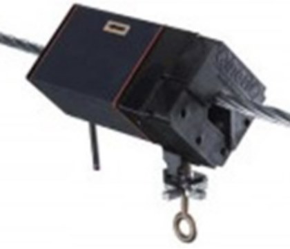
- Arc-protective devices—These sacrificial masses of metal attach to the ends where conductor covering is stripped (or other locations where conductor movement is inhibited). The arc end attaches to the mass of metal, which has a large enough volume to withstand much more arcing than the conductor itself. EPRI testing showed that arc protective devices are effective at eliminating conductor damage if they are applied right where the covering is stripped (EPRI 1017839, 2010 2); the arc anchors on the device and protects the conductor. If there is a gap between the device and the covering, the arc will motor past the device and burn down the wire where the arc attaches in the gap. Crews should place these on the downstream side of the exposed conductor, or place them on both ends for scenarios where the line could be fed from either end.
- Block reclosing—Multiple reclose attempts will increase fault duration. Blocking reclosing can prevent live, downed conductors. Even if a conductor burns down, blocking reclosing will prevent the downed conductor from becoming energized. This may or may not prevent wildfire ignitions (the downed conductor will still be very hot from the arcing damage; it is unknown what this does to the probability of ignition).
- Apply single-phase reclosers carefully—Whether hydraulic reclosers or newer cutout-mounted devices, using reclosers instead of fuses can lead to more scenarios with live downed conductors. First, some of these devices operate slower than a fuse. Second, reclosing can energize a downed conductor. Coordinate devices with burndown curves as outlined below.
- Hot-line tag—A relay settings group that trips faster and blocks reclosing will help in the case of workers near coverup. In periods of high wildfire risk, a similar settings group can be used to protect against arc-damaging faults. Protect or remove inhibiting equipment—Don’t leave line hose on conductors without arc-protective devices.
Online Calculator
To evaluate likelihood of burndowns, an online calculator is available to compare conductor damage with relay/fuse clearing times. This is based on data and models from (EPRI 1017839, 2010 2). This calculator can produce burndown/damage curves than can be coordinated with fuse curves, recloser curves, or relay curves. Proper coordination is for a protective device to clear before the given conductor is damaged.
This calculator allows engineers to evaluate solution options such as faster clearing times, and it allows comparing the coordination of protective devices with different conductors. Conductor curves are provided for bare and for covered conductors. To evaluate scenarios with line hose or other equipment that can restrict arc movement, use the covered conductors.
Utility Discussion
In the following video meeting, we discuss burndowns and coordination with a utility. Topics include covered wire and use of reclosers for taps.
Web meeting (funding EPRI members only)
Additional Information
EPRI 1018694, Distribution Arc Flash, Electric Power Research Institute, Palo Alto, CA, 2009.
EPRI 1017839, Distribution Conductor Burndown Test Results: Small Bare and Large Covered Conductor, Electric Power Research Institute, Palo Alto, CA, 2009.
T. A. Short, Electric Power Distribution Handbook, 2ed, CRC Press, 2014.
Contact Tom Short (tshort@epri.com) for more information.