Protective Device Communication
Risk Reduction Category
Technology Description
Communication (e.g., pilot wire, fiber optics, etc) has been used on transmission protective devices for many years. And recently, distribution protective devices also use communication for specific applications. Just as high-speed tripping is important to the stable and secure operation of the bulk transmission system, it is important to the distribution system, although for different reasons. Individual customers have operating systems that require reliable power. There are also voltage conditions that can be aggravated by delayed fault clearing. For example, in areas with a large amount of air conditioning load or induction generators, such as some older wind farms, the drop in voltage caused by a fault can initiate a voltage collapse [1] [2].
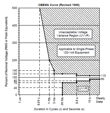
In the case of the distribution feeder to the industrial load, system frequency stability is not a consideration; however, other factors may necessitate high-speed tripping. The most important factor may be keeping motors in the factory online. The Information Technology Industry Council has established a curve, the CBEMA curve, shown in Fig. 1, that indicates a generally acceptable voltage range for power delivery [2].
Powerline carrier (PLC) has been available for many years in the transmission system. According to Aclara, a Hubbell company, more than 400 utilities use their product, TWACS® to collect revenue-critical meter data as well as monitor line conditions, detect faults or outages and monitor power restoration [5]. The technology has other uses such as real-time pricing and demand response [5].
Repurposing existing PLC technology or developing new PLC signaling technologies is an R&D question. Field trials with an active power line carrier or other signal injection technology may help manufacturers bridge the performance gap that today’s options yield. The concept is that a low-cost signal injection system (for example a variation of TWACS repurposed for protection) could be applied to the power distribution system and all the “listening” protective devices could appropriately respond in a coordinated way to de-energize the live downed conductor section.
The following list of manufacturers is the product of an Internet search using a general description of the technology as the search term. Sometimes more than one variation on the search term is used. The objective is to identify the most demonstration-ready products available in the category. Toward assessing demonstration readiness, the manufacturer websites typically provide useful information such as writeups of successful use cases or field demonstrations, number of deployments, or other indicators. Where lack of information exists online, further inquiry is made by phone. Generally, one to three frontrunners emerge as being most ready for a field demonstration. Preference is given to manufacturers who sell to the United States, or, if emerging technology, those who have participated in US-based field demonstrations.

Figure 1: CBEMA Curve
The problem of the operating speed requirement is compounded by the speed of the distribution breaker as compared to the transmission breaker. While typical transmission breakers will interrupt fault current in 2 or at most 3 cycles, distribution breakers will usually have an interrupt time of 5 cycles. This leaves a total of 5 cycles for the relaying system on the incoming distribution feeder to operate for a fault to make sure the voltage recovers quickly enough to prevent motor contactors from dropping out [2].
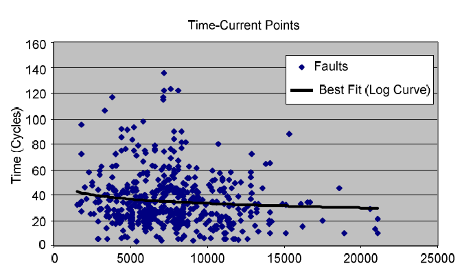
The problem that comes up is one of coordination. Even though these overcurrent units can operate with the speed required, under practical conditions of coordinating with downstream devices, the speed is much reduced. Fig. 2 shows operating times of a 34.5 kV overcurrent-based fault clearing at a large utility [3]. These are all the faults on the entire 34.5 kV network during an 18-month period.

Figure 2: Fault Clearing Times (cycles vs. Fault Current [amps])
As can be seen, the average clearing time for a 10 kA fault is in excess of 30 cycles. In fact, only 32 out of 535 faults on lines with overcurrent relaying were cleared in 10 cycles or less.
Clearly, then, overcurrent relaying is generally not able to operate fast enough to prevent major costs from being incurred at industrial loads on a distribution system. To get the necessary speed, some form of communications-assisted tripping scheme is necessary [2]. This is critical also to the amount of energy that is supplied to a fault, that potentially is an ignition source. Shortening the fault clearing times on distribution, then is important for wildfire mitigation.
Choices for distribution system communications to improve operating times can include one or all of the following:
- Direct pilot wire.
- Leased direct phone line.
- Leased digital phone line—channel service unit/data
- service unit (CSU/DSU).
- Direct fiber-optic cable.
- Multiplexed fiber-optic cable.
- Licensed radio.
- Spread-spectrum radio [2].
Some typical operation times are shown in the following table (Table VI from reference 2).
| Protection Scheme Comparison | |||
|---|---|---|---|
| POTT | DCB | Current Differential | |
| Operating Speed | High (1.5 to 2 cycles) | Medium to high (2 to 2.5 cycles) | Very high (1 to 1.5 cycles) |
| Loss of signal consequence | Failure to trip | False trip | False trip |
| Loss of signal mitigation | Add trip window | Continuous channel monitor | Continuous channel monitor |
When applying communications-assisted protection schemes to distribution applications, the following should be considered:
- In order to ensure protection quality, communications should be monitored during normal and trip conditions and alarmed for prolonged failures.
- The protection scheme must consider the speed and quality of the communications system.
- Backup protection, even if contained in the primary relay, must be designed with consideration of the anticipated failure mode and rate of the communications system.
- Protection logic values need to be assigned for the condition of channel failure to reduce possible false trips and failures to trip.
Technical Readiness (Commercial Availability)
Protective devices with communications are available from such vendors as SEL, GE, and ABB.
Among many others
Implementations / Deployments
Although initially published in the early 2000s there have been increasing numbers of deployments of distribution protective devices for years, especially with utility-scale DER.
References
[1] J. Roberts, T. L. Stulo, and A. Reyes, “Sympathetic Tripping Problem Analysis and Solutions,” proceedings of the 24th Annual Western Protective Relay Conference, Spokane, WA, October 1997.
[2] Roy Moxley and Ken Fodero (SEL), “High-Speed Distribution Protection Made Easy: Communications- Assisted Protection Schemes for Distribution Applications”, SEL Journal of Reliable Power, Volume 3, Number 2, August 2012.
[3] R. Moxley, “Analyze Relay Fault Data to Improve Service Reliability,” proceedings of the 30th Annual Western Protective Relay Conference, Spokane, WA, October 2003.