Drone Imagery for Utility Inspection
Introduction
This page is designed to assist a drone photographer in taking useful inspection images of overhead assets. It introduces general photography fundamentals and common camera settings. Starter settings are recommended, as well as several workflow factors that might inform a different choice of settings.
Photography basics
Inspectors need clear, focused, and adequately illuminated images of the objects of interest. Several camera controls and settings can be manipulated to achieve the desired results.
Exposure
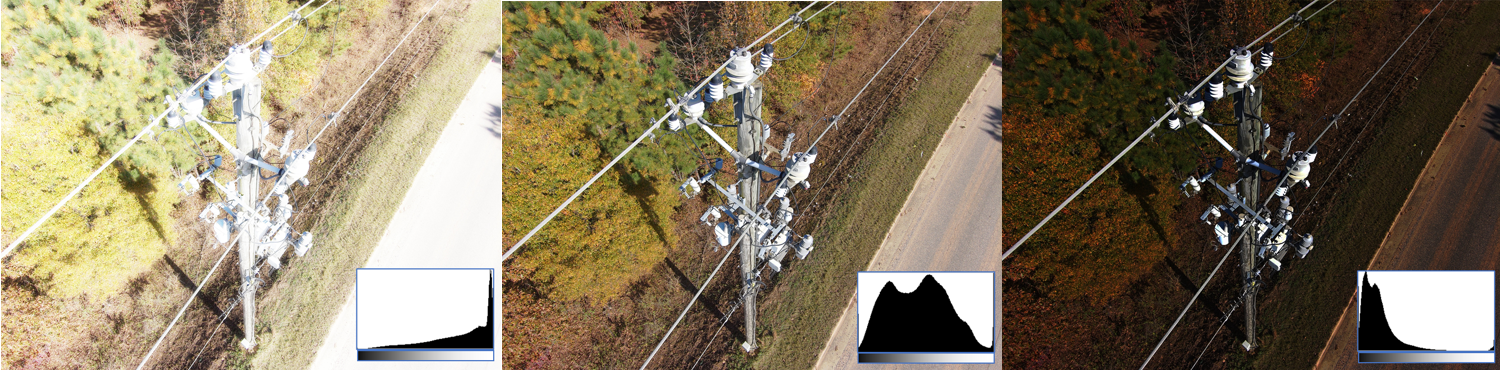
Exposure is the amount of light that reaches the camera sensor. Over-exposed images are too bright, while under-exposed images can be too dark to see.
An image’s exposure is controlled by the camera’s aperture, shutter speed, and ISO value:
|
|
The aperture is the opening that determines how much light enters the camera. It's measured in f-stops, where a lower f-stop corresponds to a larger diameter and allows more light to enter the camera than a higher f-stop. The aperture setting also impacts the depth of field.
|
|
|
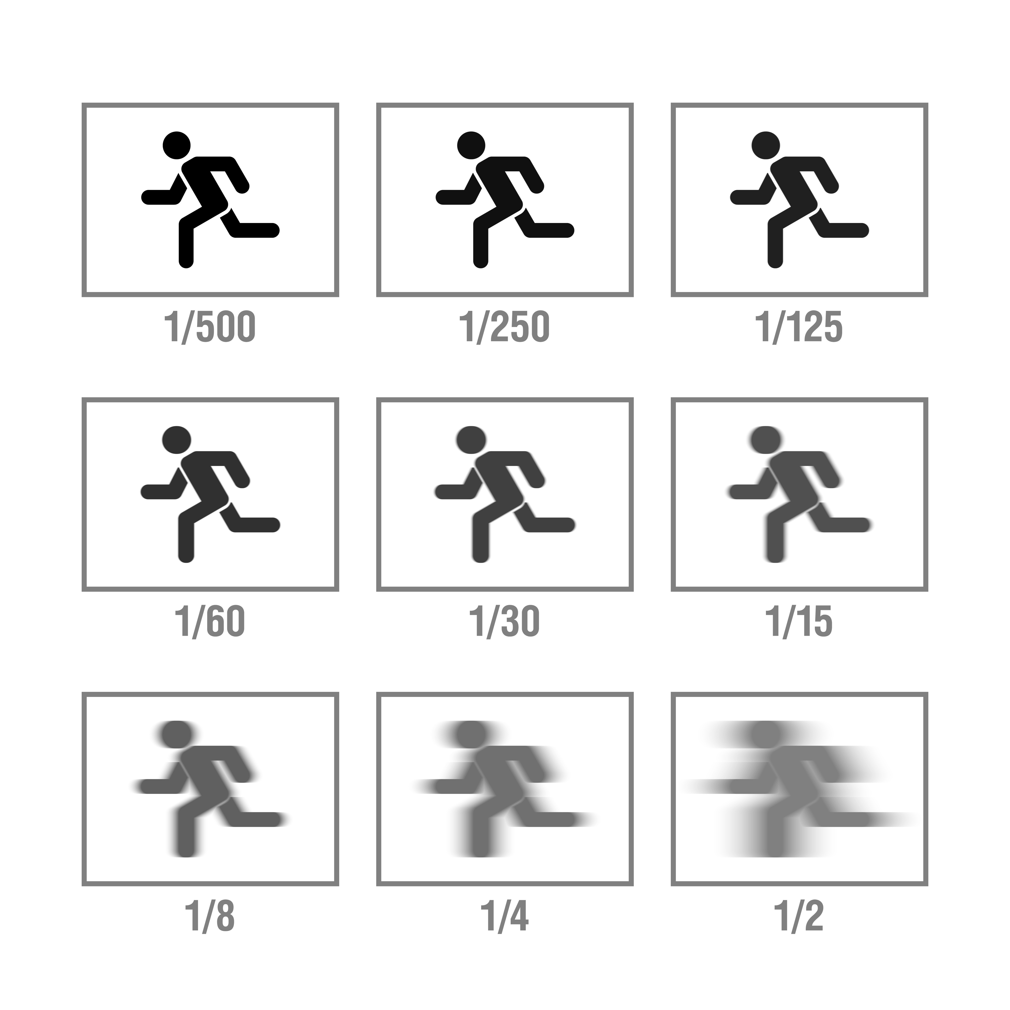
The shutter speed controls the image exposure duration. The shutter opens and closes, controlling the duration light is permitted to enter the camera - the "exposure time". It's usually measured in fractions of a second. Longer exposure times permit more light to reach the sensor than shorter exposures, however slow shutter speeds can result in blurs due to motion of the drone or any image subject.
|
|
|
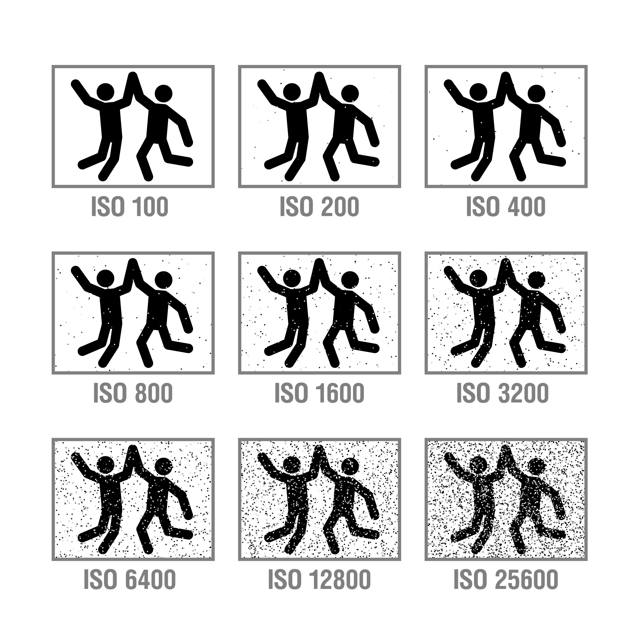
A camera's ISO setting determines the sensor's sensitivity to light. Lower ISO settings are less sensitive to light than higher ISO settings. Increasing the ISO can help to capture images in low light conditions, however higher ISO settings also increase the noise in a photograph. It's generally recommended to use an ISO lower than 400.
|

Depth of field
|
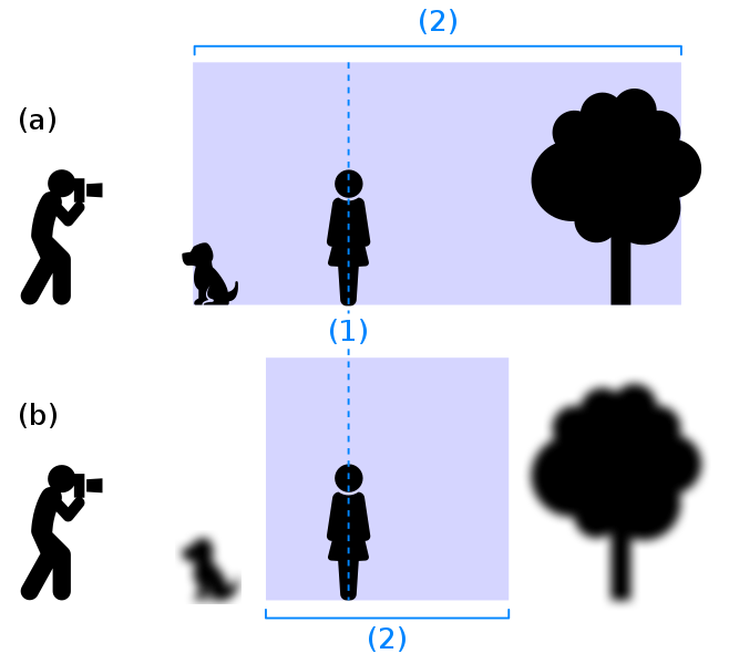
The range of distances from the camera that are in focus is referred to as the depth of field. A common example of the use of depth of field is the portrait modes on many modern phone cameras, which simulate a shallow depth of field where only the subject is in focus.
The depth of field can be adjusted via the aperture setting. Higher f-stops will focus a wider range of distances than small f-stops. The camera's focal length also impacts the depth of field. Short, wide-angle lenses tend to have larger field depths than longer focal lengths. A large depth of field is generally best for drone photography since it allows more objects of different distances to be in focus in a single image. |
|
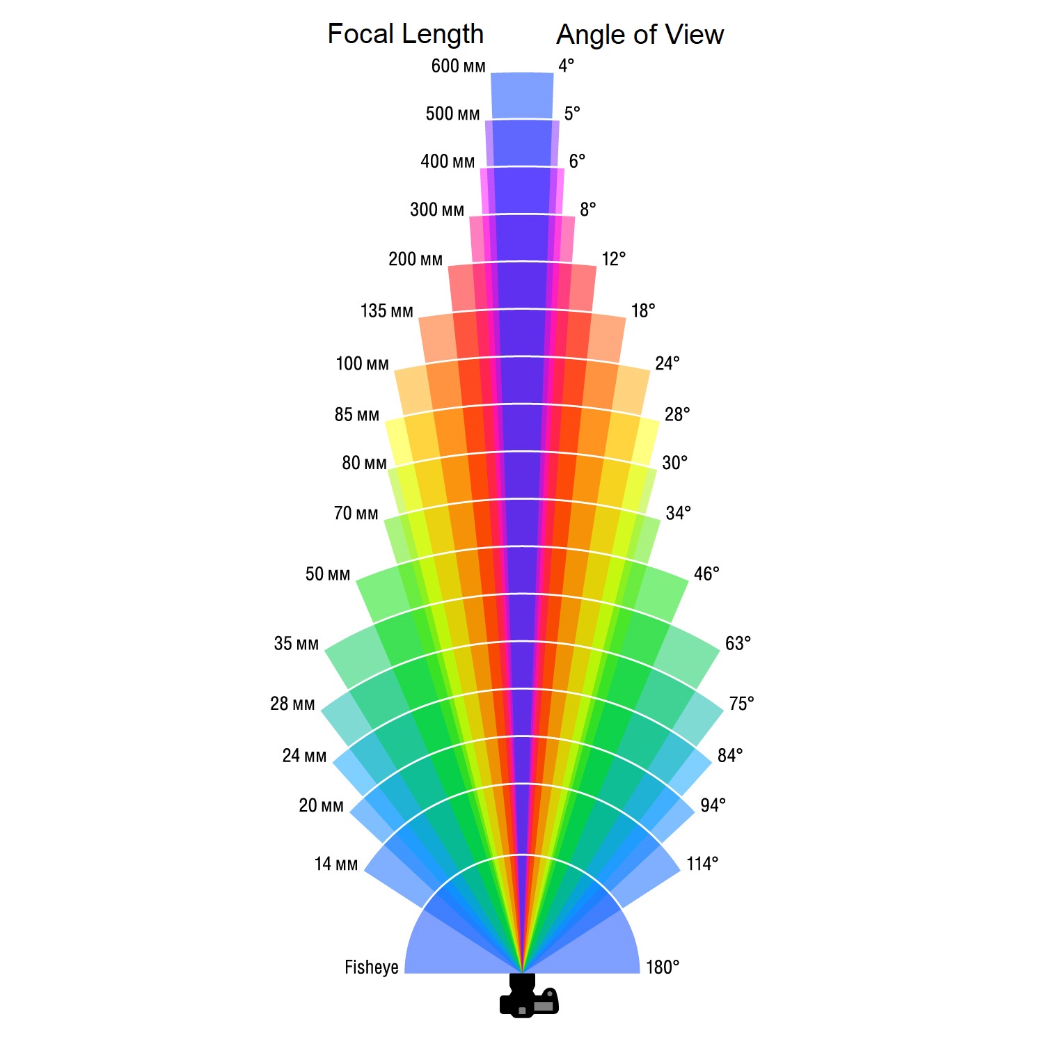
Focal length
The focal length is a property of the camera lens. Some lenses have fixed focal lengths, while others can be adjusted, allowing the photographer to zoom in and decrease the angle of view.
Camera tools and settings
Focus
Most cameras have both auto focus and manual focus settings. Autofocus is helpful, but it does not always choose the correct object to focus on. Some camera screens allow the user to tap on the picture to control the focus point. In instances where the camera does not automatically focus on the object of interest, it may be necessary to adjust the focus manually.
Exposure
A drone photographer has many settings through which to control the exposure:
Manual Exposure - the photographer manually sets the aperture, shutter speed, and ISO
Auto Exposure - the camera chooses the aperture, shutter speed, and ISO settings
Priority Exposure - there are two common priority modes: aperture priority and shutter priority. In the aperture priority mode, the photographer chooses the aperture setting while the camera sets the shutter speed and ISO. Shutter priority lets the user control the shutter speed while the camera determines the aperture and ISO.
Exposure Compensation - For exposure modes where the camera selects some or all of the exposure variables, exposure compensation can be used to adjust the image brightness targeted by the camera. This is often designated as EV for exposure value.
Exposure Bracketing - This is a fuction that takes images at different exposures. The images can be used individually or stitched together later in post-processing.
High Dynamic Range (HDR) - This function takes images at different exposure and then automatically stitches them together into one final image.
Image shape, size, and format
JPEG and RAW are image file formats offered by many cameras:
JPEG files do not require special software to view or edit. They are also compressed, meaning the files are smaller, so more will fit on the drone’s SD card.
RAW files are uncompressed, meaning they preserve the original image quality but are larger than compressed formats like JPEGs. The additional detail preserved in a RAW image can be useful, particularly if the image is edited in a program such ase photoshop.
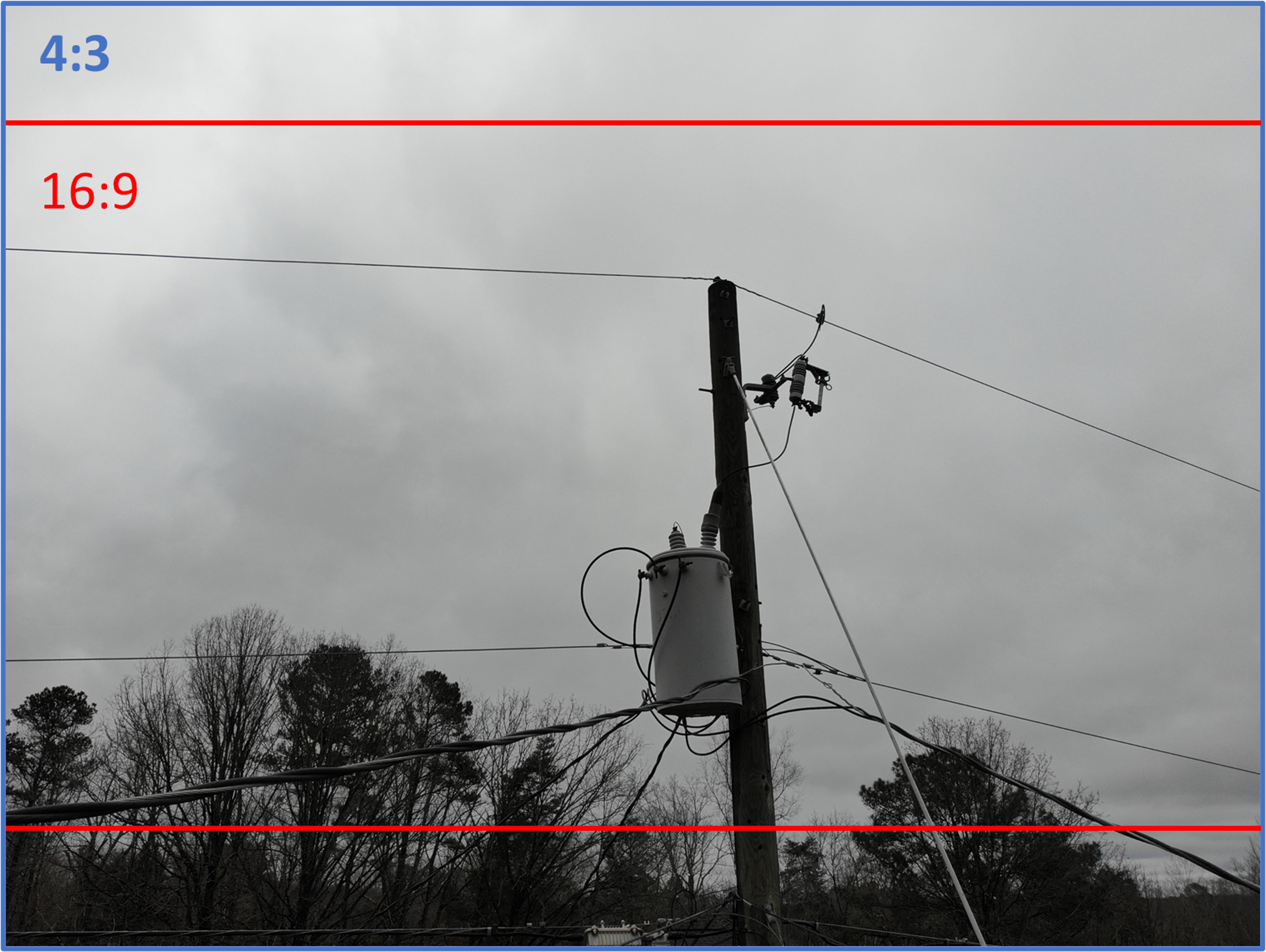
Aspect Ratio The aspect ratio dictates the shape of the final image. Options often include 16:9 and 4:3, which are the ratio of the images width to height. Unless the object is very wide within the field of view, 4:3 generally fits objects in the frame better than 16:9.
Choosing settings
Considerations
-
What is the lightning at the time of the flight? Different weather conditions result in a variety of lighting conditions. Direct sunlight can brightly illuminate an object but also cause shadows. Shadows present a challenge when ensuring all parts of the relevant components are correctly exposed. Overcast skies are less likely to cause harsh shadows but generally provide brighter backgrounds. Some digital cameras provide white balance settings to accommodate for the color of the light source. Specifically, common settings that apply for outdoor inspection include ‘direct sunlight’ and ‘cloudy’ conditions. Auto exposure bracketing and high dynamic range images can help improve image quality. These techniques are useful when inspection an object in direct sun with shadows.
-
Are the images going to be processed after they are taken? Post processing techniques can adjust the brightness of the image, or blur background objects. Workflows that include post-processing have more flexibility to make use of poorly exposed images. If post processing is not preferred, photographers should adjust the exposure settings in real-time to capture properly exposed imagery. Note that post processing techniques usually cannot correct objects out of focus.
-
Are there file storage constraints? The file size allotted for each image is determined by file storage available (on an SD card, for example) and the number of objects to be photographed. Several settings impact the file size. Some of these settings include: RAW formats, HDR photos, and AEB images.
Recommended starter settings
- Auto Exposure
- Auto Focus
- RAW (only if post-processing AND enough space on the SD card)
- 4:3 aspect ratio at the camera’s highest resolution
If shadows present an exposure challenge, try:
- Exposure bracketing if you have plenty of storage space
- High Dynamic Range (HDR) if you do NOT have plenty of storage space
Basic image troubleshooting
Photographers should double-check that the details in the objects of interest are clear. If they aren’t, try:
- Adjusting the camera focus
- Moving closer to the object
- Increasing the shutter speed
- Decreasing the ISO sensitivity
- Changing the exposure compensation
Positioning the camera
Reference and orientation
When discussing image orientation to the structure, it can be helpful to define position references.
A Three-dimensional axis system (x,y,z) can be defined based on the direcion of the conductors and the pole. For example, the z-axis can be defined as the pole height, the y-axis can be the direction of the conductors, and the x-axis will usually be parallel to the crossarm.
Additionally, a quadrant system might be helpful if looking directly down on the structure and height regions can be used to seperate photos taken of the structure top as opposed to underbuild or the pole base.
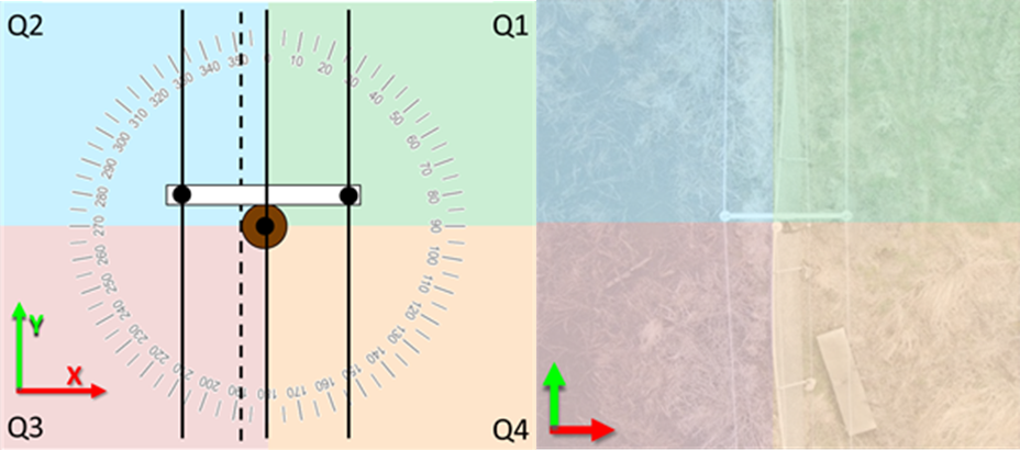
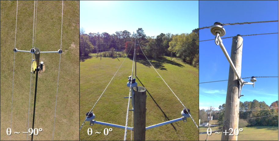
Camera azimuth and pitch represent the angle of the camera in relation to the coordinate system. The azimuth is the angle of the image taken while looking down on the structure; the angle around the z-axis. The pitch is the angle of the camera relative to the horizon.
Perspective
A drone camera can photograph an object from several different positions and angles. The viewing angles (perspectives) used can impact the number of photos required to inspect a structure.
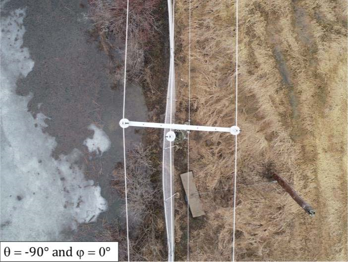
A Nadir perspective is directly above the object being photographed. Nadir images of poles can be useful for both perspective and geolocation purposes.
Oblique images, taken at an angle to the object, are also useful as it’s less likely that objects in the foreground will obstruct objects in the background.
Spatial Resolution
An image’s spatial resolution is often expressed as ground sampling distance (GSD), which is defined as the center-to-center distance between pixels measured on the ground. A good rule of thumb is to capture half the GSD than the smallest object of interest. For example, if cotter pin thickness is 0.5 cm, capturing 0.25-cm GSD would provide at least 4 pixels of the pin. Smaller items like cracks in porcelain may require sub-millimeter GSD while broken poles can be identified with approximately 5-cm GSD.
GSD is a function of the distance to the image subject (or ground), the camera’s sensor size and pixel size, and the focal length of the lens. The GSD of the below images are estimated using the drone manufacturer’s camera calibration and the measured distance between the camera and the structure.
|
|
|
|
Frame coverage
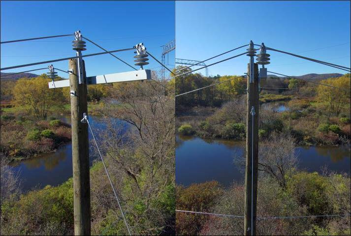
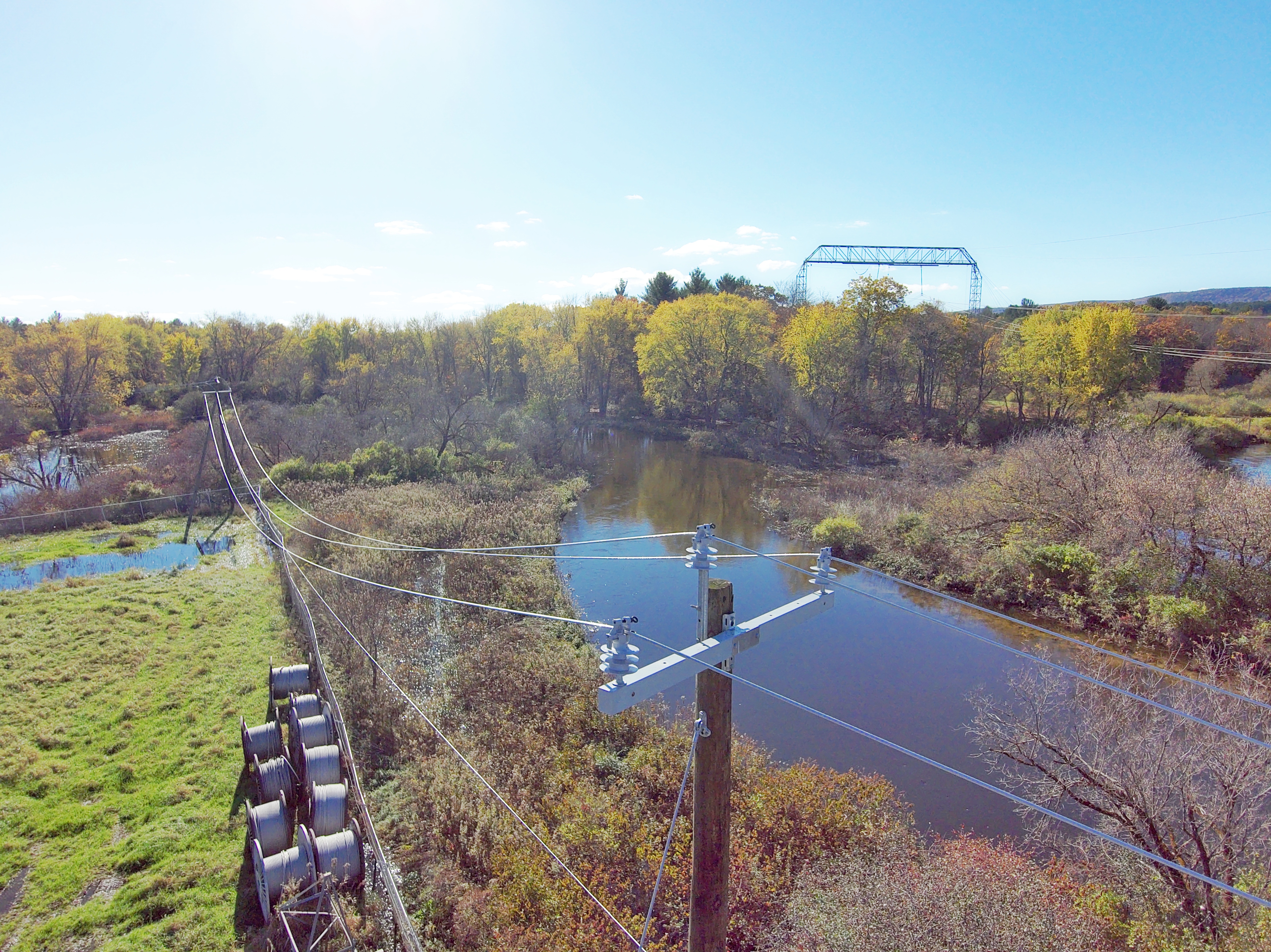
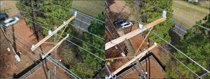
Image frame coverage (FC) characteristics should be considered when performing inspections. FC is the dimension of a rectangular area, frame height (FH) by frame width (FW) covered by an image frame for a plane orthogonal to the d-vector (i.e., distance and direction from the camera to an object). Inspectors should capture the minimal number of images to complete the work. Poor framing may impact the inspection quality or increase the number of images to complete the work. The image on the left properly shows the full view of the crossarm. However, the image on the right truncates the crossarm, thus requiring another image from the same perspective.
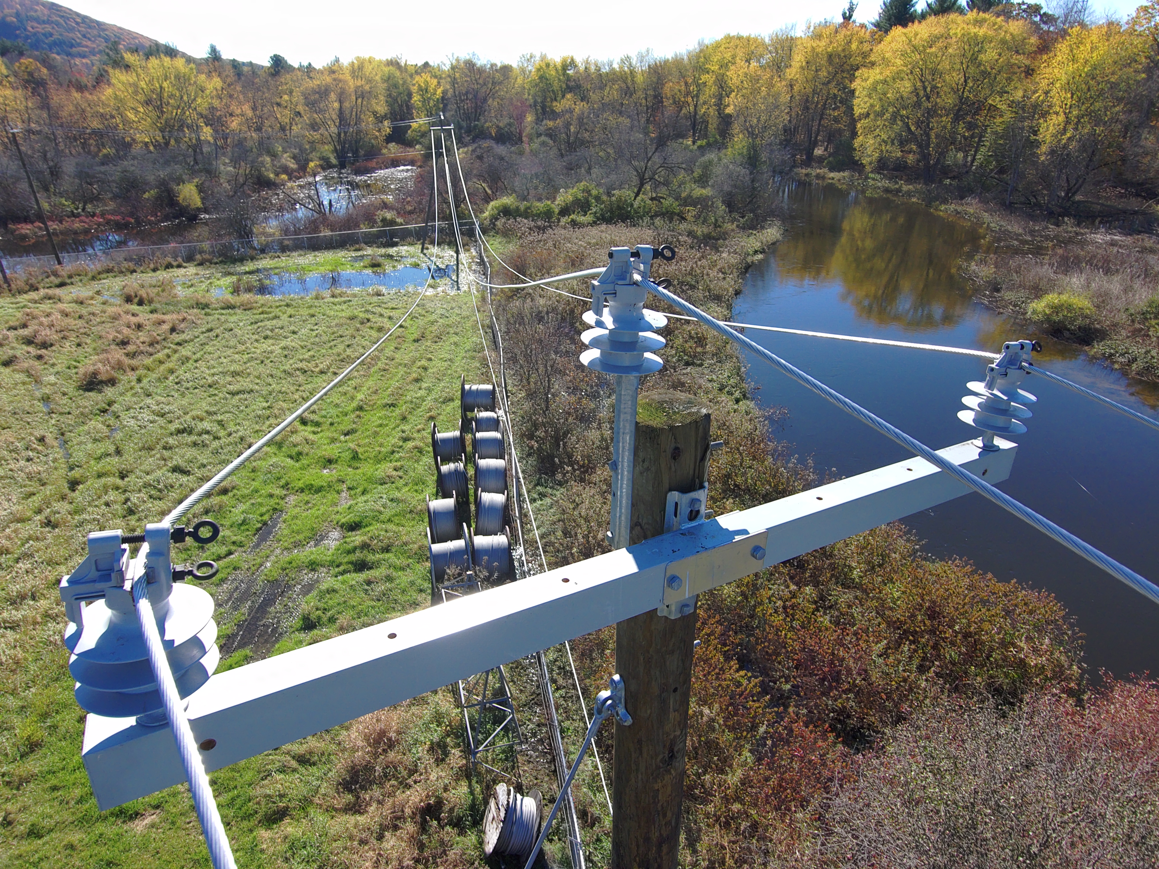
Utilities may consider adjacent poles or structure components for framing as well. For example, consider the foreground pole (Pole A) and background pole (Pole B) in this image. One framing specification may require the top of Pole B at the top of the image frame, and the neutral connection of the Pole A towards the bottom of the image frame. This helps identify any phase transitions.
Example shotsheets
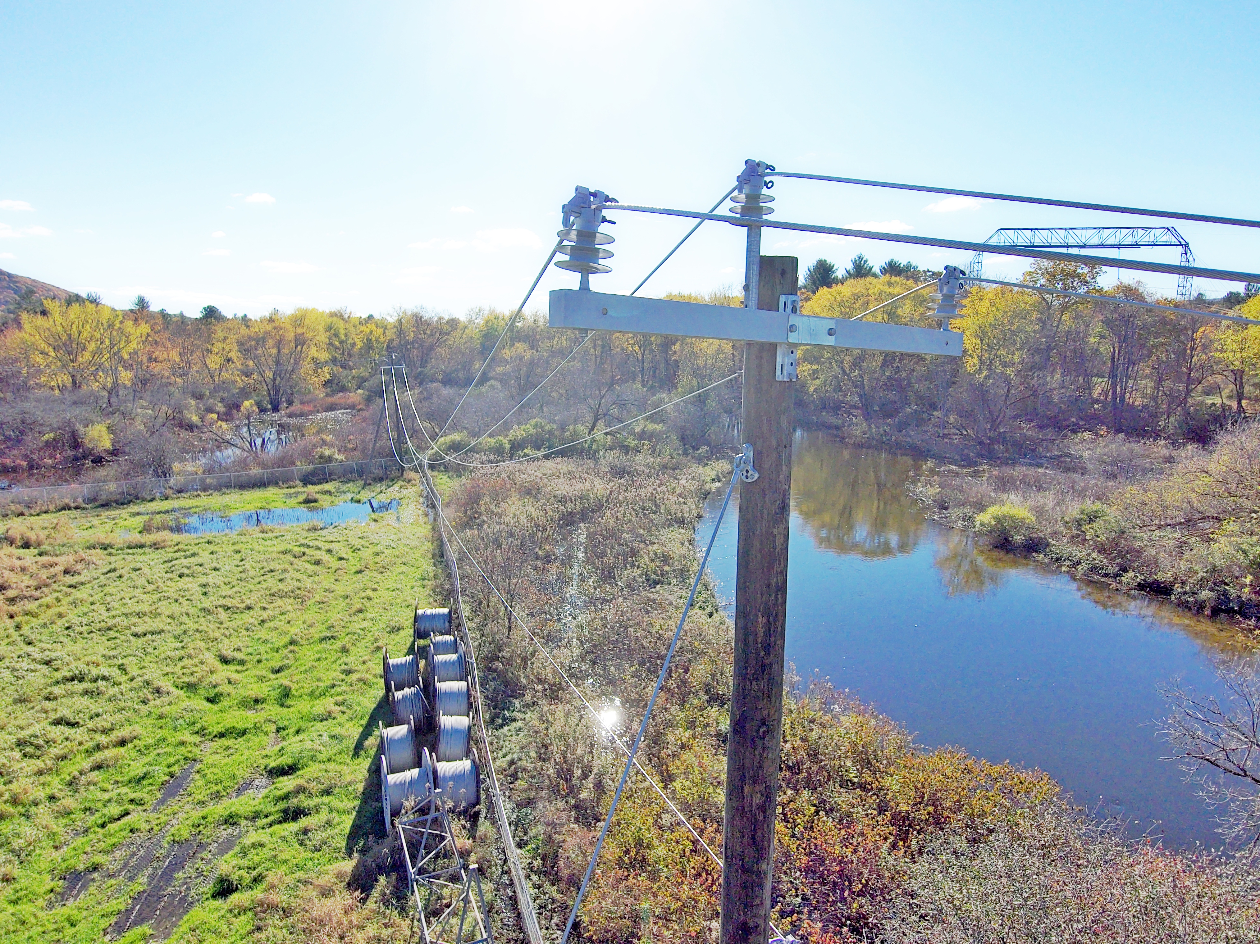
Shotsheets are jargon for the image capture specifications. They provide instructions for the drone operators on how to frame the structure. They may even provide a cadence or order on how to capture the different perspectives. When building shotsheets, utilities should consider the end goal and the minimal number of perspectives to meet that goal. Additionally, utilities should recognize that the ability to capture multiple perspectives may be limited by the environment. Limitations can include narrow rights-of-way from vegetation, adjacent roadways, homes, or other factors. Utilities should consider the aircraft flight profile that best suits the environment. Figure 23 shows two extreme environments. The picture on the top shows a narrow ROW. A drone is likely limited to flights directly over the conductor due to the vegetation obstructions. The picture on the bottom shows an open field environment with little to no limitations.
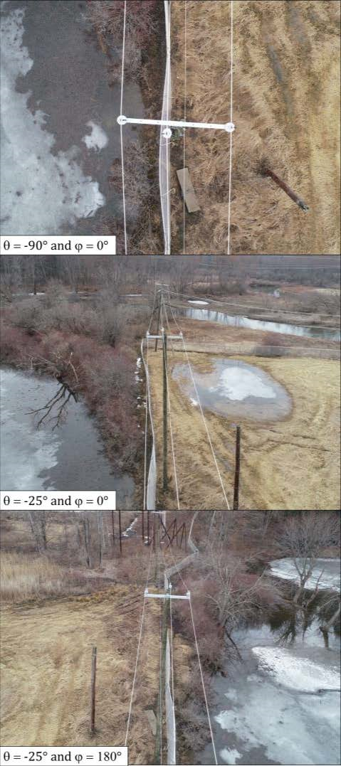
3-Shot technique
The 3-shot technique combines a front, back, and nadir image capture. This method is useful in narrow rights-of-way. It also reduces the time required to capture the imagery. With only three images, its recommended to frame the entire pole in the field of view. Below are examples of nadir shots with front and back views of the pole from the base (H1) to the pole top (H3).
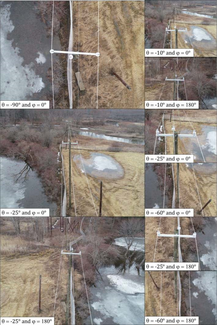
9-Shot technique
The aircraft flight profile is like the 3-shot technique. However, these frames add additional images for more resolution of the pole at multiple heights. This results in nine total images. Utilities should consider this method if they need a lower GSD to perform the inspection or want to see the adjacent structures. Note that the pitch to capture similar frames is related to the aircraft position above the structure. It’s likely there are several pitch values that result in useable imagery. These images provide a front and back few of the foreground structure as well as the adjacent, background structure.
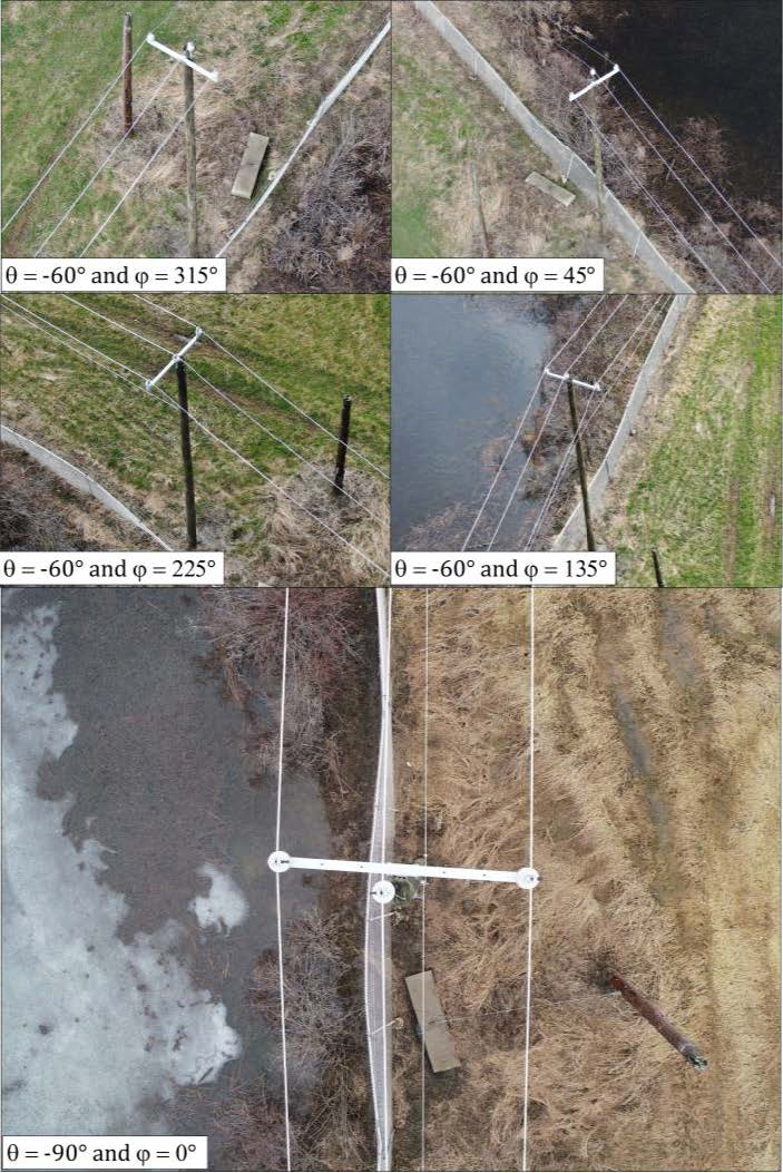
5-Shot technique
For open rights-of-way with low aircraft obstructions, consider the 5-shot technique. These five images combine a nadir view with oblique imagery from the four quadrants. This method provides a full view of the pole. If performed optimally, this could result in approximately 25% overlap between each image perspective. With the limited number of images, its recommended to frame the entire pole (H1, H2, H3) in the field of view.
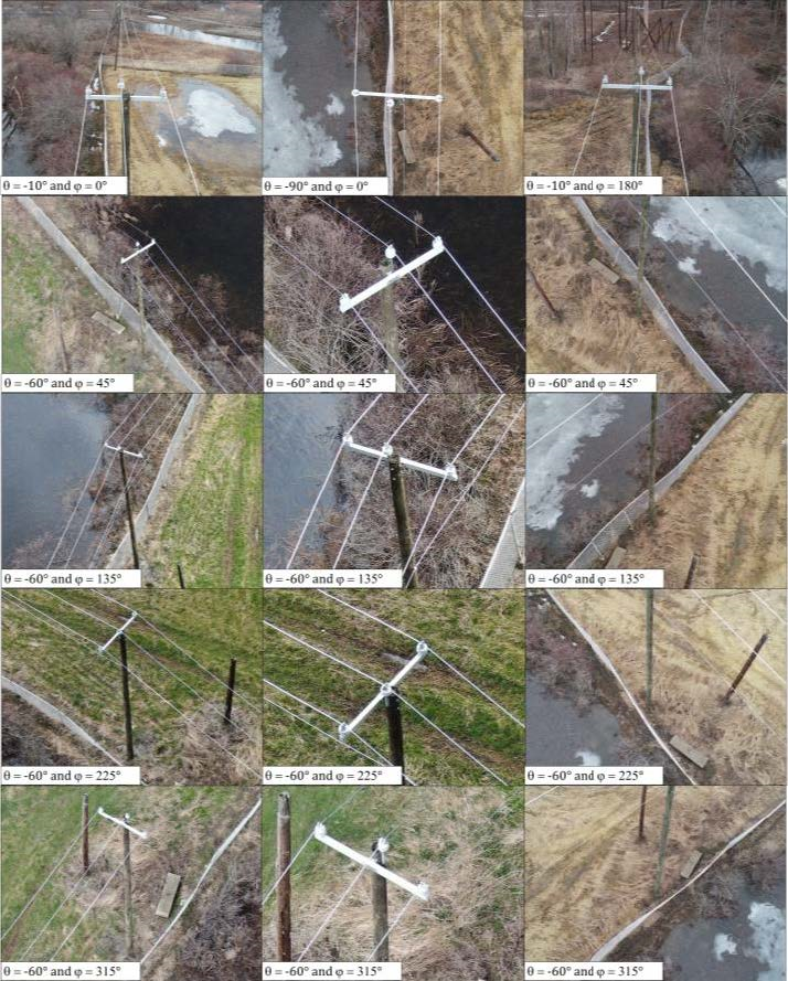
15-shot technique
Depending on the resolution requirements, inspectors may need more pictures to inspect the components. This is an expansion of the 5-shot technique, but with more resolution at different pole heights.
Additional considerations
Shotsheets may vary based on pole configuration or installed equipment. Utilities should develop these shotsheets, or image capture specifications, to improve inspection quality and consistency.
- Inspectors should know how to handle environmental limitations or contingencies. Also, they should develop a flight profile that optimizes the flight path to capture the required imagery.
- A defined cadence or order of shots may support post data review and storage workflows. For example, if the inspection began or ended with the nadir capture, that could be used to identify which imagery corresponded to which pole.
- Geospatial data management tools with oriented image viewers may add benefit for a post-inspection workflow.